
UNDER CONSTRUCTION
To do long range seismology you have to know what time it is. You have
to know exactly what time it is. Everywhere. Most of the Digital
Acquisition System (DAS) recorders used by PASSCAL have built-in GNSS
receivers (GPSR). Most of the DASs have connection points to allow
using external antennas. The DAS is usually in a protective box with
the antenna placed outside.
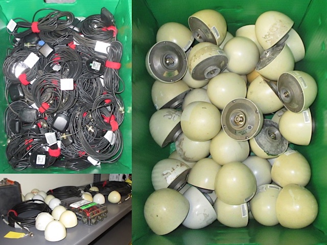
PASSCAL has hundreds of GPS antennas. There are several different pieces of equipment for testing the coaxial cables that connect the antennas to the DASs, but testing the antennas themselves has always been a bit sketchy.
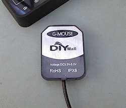
Development of the testing system software started in early 2022 by using G-MOUSE GNSS receivers that had been acquired for the GPSVIEW repeater monitoring system. They are the four units on the left in the picture above. These are u-blox brand receivers and antennas built into one small package. Each unit is powered by a standard USB port and transmission of the NMEA sentences is by serial COM ports (Windows) or tty.usbmodem devices (Linux/macOS).
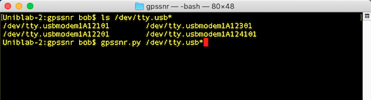
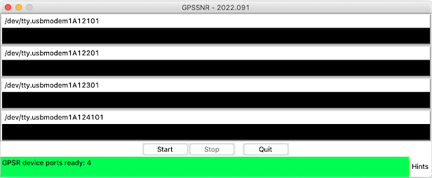
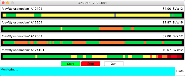
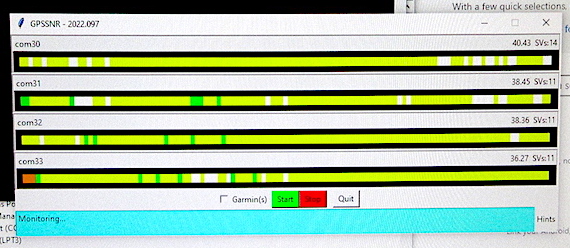
The Python software application developed for this is gpssnr.py. It plots the average satellite signal-to-noise ratio values for as many GPSR devices as are specified on the command line when the program is started. NMEA sentences generated by receivers are read and the plots are updated each second.
Monitoring the NMEA sentences is started by clicking the Start button. The plots fill in right to left with one block being added to the right each second. Up to 120 seconds of data points will be displayed then scrolling will continue to the left.
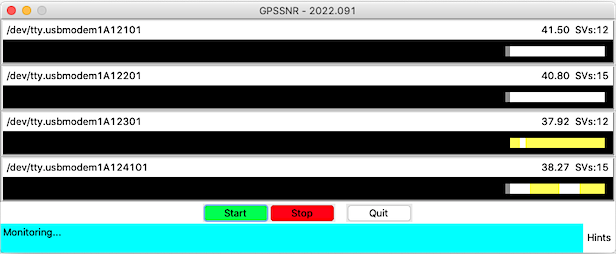
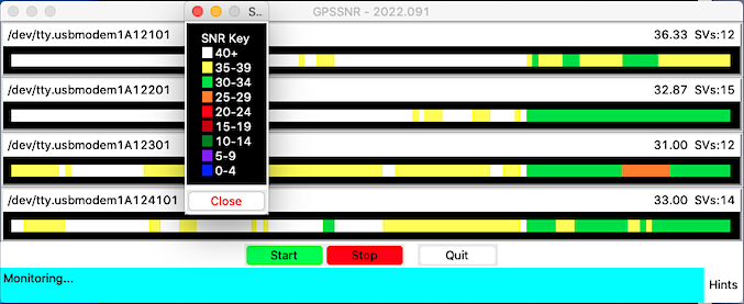
The average SNR of all of the satellites for each receiver each second is listed above the plots. The number of space vehicles (SVs) used in the calculation is also listed. The color of each second's block is set depending on the value of the SNR average. The color key is shown by control-clicking on any SNR plot.
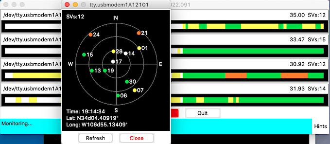
An SV Target display showing the position and SNR for each satellite can be brought up by clicking on a plot. This display shows the number of space vehicles visible to the receiver, so this number may differ from the SV number on the SNR plot. Satellites whose position information is not yet known will be plotted below the "N" (0° el, 0° az). The display is static, so the Refresh button must be used each time to update the plot.
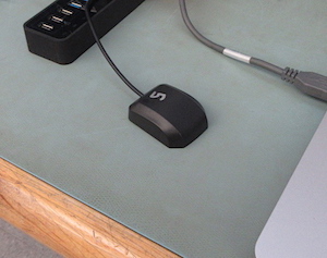
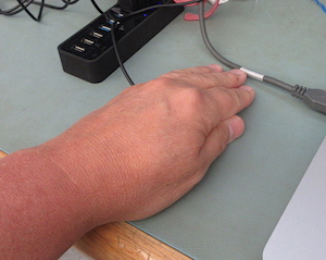
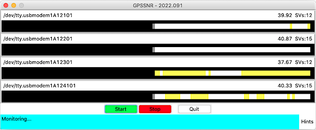
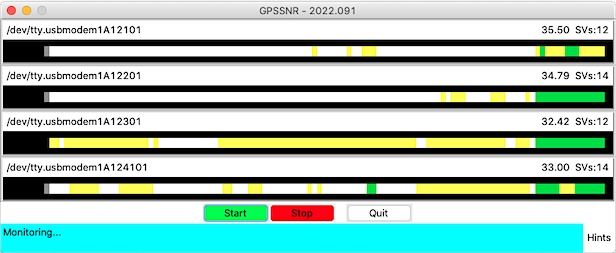
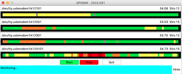
The point of this whole exercise is to show the relative strength of the satellite signals from several antennas at the same time. Doing this will allow antennas with "weak" or non-functional amplifiers to be selected and repaired, or removed from service. Above, when I place my hand over the receiver, the SNR of that receiver changes in seconds as seen below.
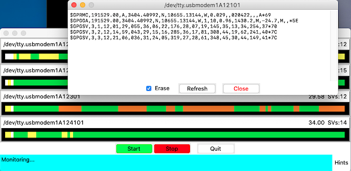
Shift-clicking on an SNR plot will bring up a form showing the NMEA sentences from the second when the plot was clicked on. This shows all sentences transmitted by the receiver, and not just the $GPRMC/$GNRMC and $GPGSV sentences used by the application.
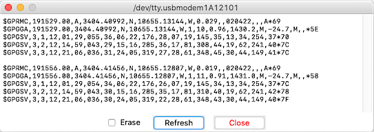
Deselecting the Erase button will update the form with new sentences without erasing the previous sentences.
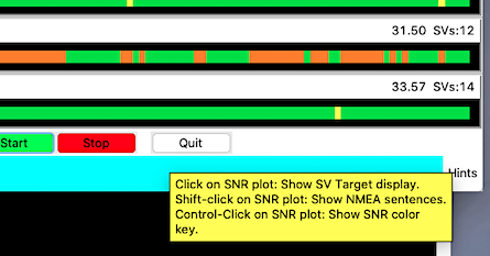
Mousing over the Hints label simply shows a tooltip with the three possible functions of clicking on the SNR plots.
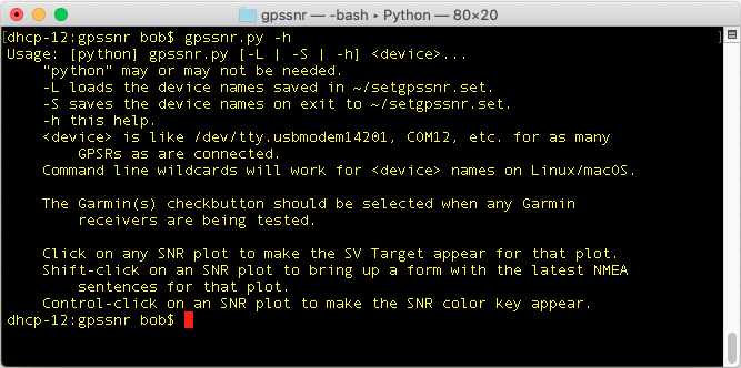
The -h argument on the command line will show a short help
message.
The -S command will save the provided list of devices to the
file setgpssnr.set in the home directory. The next time the
program is started the -L command can be used, instead of
typing the device names, and that list will be reloaded.
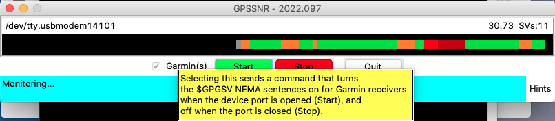
In addition to just antennas the system is designed to test Refraction Technologies (RefTek) 130 GPS antennas, which are Garmin 16X GPSR units. The units are set up to generate $GPRMC, $GPGGA, $PGRMM, $PGRMT sentences for use with the RefTek recording units. They are not set to generate $GPGSV ones, which contain the satellite information the program needs. The check button "Garmin(s)" is available when testing these GPSRs. With this button selected a command to turn these sentences on will be sent when the Start button is clicked. When the Stop button is clicked, or the program is stopped or quit, the command to turn those sentences off will be sent. The RefTek recorders do not use those sentences.
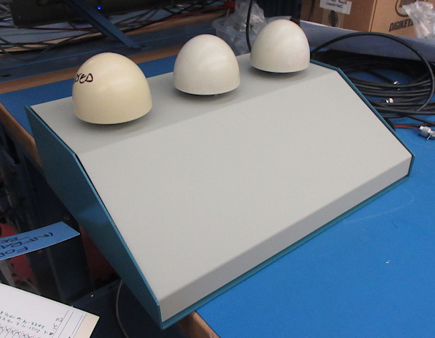
April 2022: The concept for the system is to have all of the required electronics contained in a project box like above. There will only be two USB wires coming out, and one of the standard 4-pin power connectors to supply 12VDC going in. Up to three of the Trimble "egg" antennas will be able to be tested at a time.
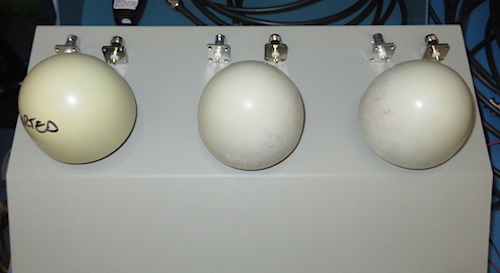
There will be a BNC and a TNC connector on top mounted behind the connectors for each of the egg antennas to test "patch" antennas that normally cannot be removed from their cables.
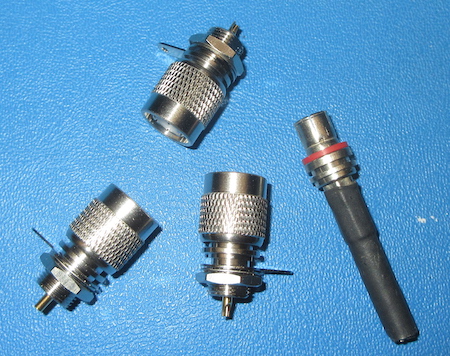
The Trimble antennas will be placed on male TNC connectors that have had their knurled knobs removed so the antennas can be slipped on and off. The connector on the right above is the end of a cable whose connector has been operated on.
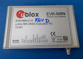
The GPSRs selected for this project are u-blox EVK-M8N evaluation units. They locked up right out of the box and only needed extra satellite constellations and NMEA sentences turned off to set them up for this system.
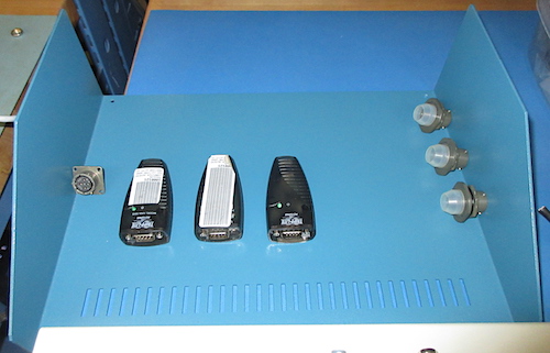
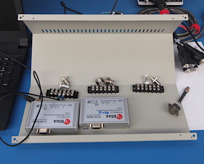
The RefTek (Garmin) GPSRs are 19200 baud serial units that will be connected to KeySpan serial to USB converters. They will show up on PCs as serial devices like the three u-blox GPSRs. In the picture above the three 8-pin Amphenol connectors that are a match for the connectors on the cables will be mounted "somewhere" on the box. The whole unit will be powered with 12VDC through a standard PASSCAL 4-pin Amphenol connector which is on the left.
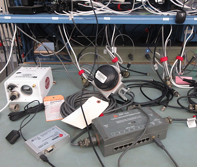
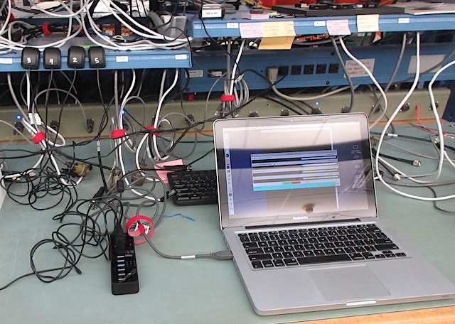
Above is just the u-blox receiver and antenna on the left, the RefTek 130 clock unit in the middle, and one of the G-MOUSE receivers in the upper right corner all running at the same time feeding info the the gpssnr.py software. The large grey box is an old GPS distribution unit that was used by the RefTek "Texan" recording system. Here it is just being used as a serial to USB converter and power supply for the receiver. The white Nanometrics Centaur and extra cables are just photo-bombing.
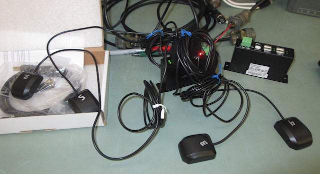
The last piece of the puzzle is two USB hubs to tie everything together. The StarTech 4-port hubs are powered by 12VDC. One hub will be for the u-blox receivers and the other for the KeySpan converters. Above is just a little testing. One of the hubs is buried under all the wires.
Just testing.

Mid-October (2022) I finally got together enough stuff to start work again.
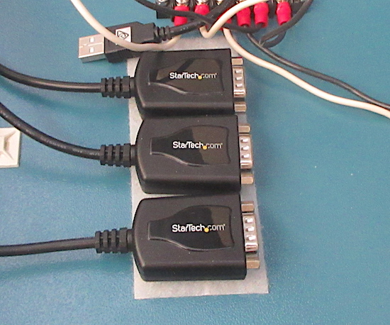
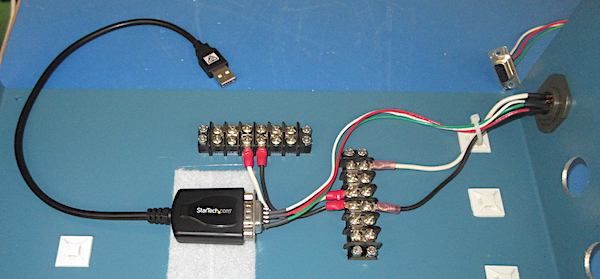
I changed from the Keyspan USB to Serial Converters to ones made StarTech.com. They were much more compact and they (surprisingly) worked better with newer versions of macOS than the Keyspan units. I'm guessing at some point with get their driver-stuff in order.

Laid out, measured and drilled many holes. Most of them even ended up the right place.
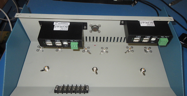
Above the top of the box is flipped upside down. The 'standard' PASSCAL 4-socket connector was placed in the middle on the back of the box. The USB hub on the left had to be up away from the bottom of the box a bit to dodge the wiring for the three USB converters and connectors for the RT130 GPS units.
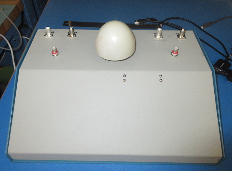
Not much to look at on the outside.

Each GPS receiver had to be connected to three different antenna connectors. That was all handled with a terminal strip.
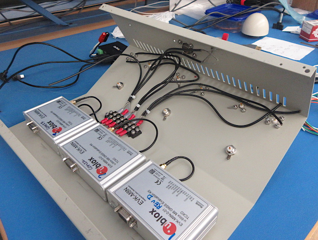
Above is all of the antenna wiring, except for the soldering.

The only connection between the top and bottom portions of the box are 12VDC power wires. I used Anderson PowerPole connectors so they could easily be disconnected from each other in case things needed to be worked on. I've used those connectors quite a bit with my telescope equipment.
8

10

9
2023-03-16